How to select frequency inverter?
These guidelines dispel the confusion about matching Frequency inverters (Variable frequency drive) and motors to fans and pumps that are typically encountered in commercial building applications. While the motivation to increase energy efficiency could be financial (reduced energy costs) or ethical (reduce greenhouse gas emissions associated with power production), it is taken for granted that frequency inverters are an easy way to improve energy efficiency in a motor application. And with these noble intentions in mind, the engineer will specify a frequency inverter for his client. Oftentimes, that isn't the end of the story for the engineer.
Ask an engineer the purpose of a frequency inverter (what is frequency inverter?), and a common answer would be "to save energy". While the motivation to increase energy efficiency could be financial (reduced energy costs) or ethical (reduce greenhouse gas emissions associated with power production), it is taken for granted that frequency inverters are an easy way to improve energy efficiency in a motor application. And with these noble intentions in mind, the engineer will specify a frequency inverter for his client.
Oftentimes, that isn't the end of the story for the engineer.
The story sometimes ends badly with a dead motor or a building with power quality issues, an understandably angry client, and a lot of finger-pointing. These outcomes are often the result of a poor understanding of how frequency inverters and motors work in conjunction with the loads they serve. The information and claims from manufacturers and vendors often serve to further confuse the issues. Following are a few basic guiding concepts to dispel some of this confusion surrounding the matching of frequency inverters and motors to fans and pumps typically encountered in commercial building applications.
Anatomy of an induction motor
Electric motors convert electrical energy into rotational mechanical energy. Motors may drive pumps, fans, compressors, or any other number of loads that may be found in a typical building. The concept seems simple, but a review of motor basics is necessary to understand how frequency inverters operate and also how they can destroy a motor.

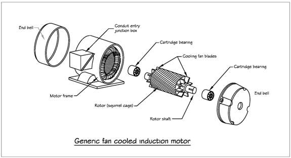
The most common motor encountered in commercial building multihorsepower applications is a 3-phase ac induction motor. The motor consists of two primary assemblies: a stationary stator and a rotating rotor. Alternating current flows through windings in the stator, creating a rotating magnetic field around the rotor. The frequency of this rotating magnetic field is directly related to the frequency of the ac voltage source. This rotating magnetic field interacts with rotor, inducing current in the rotor and an associated tangential force, which ultimately causes the rotor to turn. In an induction motor, the speed of the rotor is always slower than that of the rotating field. The torque of the motor is roughly proportional to the power of the motor and inversely proportional to the speed of rotation. This operational characteristic is important when considering if a variable torque load (centrifugal fan, pump, or compressor) or a constant torque load (positive displacement screw, scroll, or reciprocating compressor) will be connected to the motor.
The most common type of induction motor is the squirrel cage motor (also called short-circuit rotor type motor). The stator consists of doughnut-shaped sheets of steel called laminations. These laminations have slots punched in them and then are aligned and stacked together. Conductors are then wound through these slots to form coils. These coil conductors are electrically insulated from the laminations. The characteristics of this insulation system are important later in our discussion. The cylindrical rotor fits in the void in the middle of the stator. Like the stator, the rotor is made from stacked steel laminations. These laminations are pressed onto a center shaft. Bars of aluminum or copper are inserted through slots at the outer edge of the lamination and are connected at the ends with shorting rings at either end to form a cage-like structure. The rotor is supported with bearings at the ends of the shaft. There is no direct electrical connection between the rotor and the windings in the stator. The only point of contact is at the bearings, which will be important in a later section.
Induction motors are not 100 percent efficient. Motor energy loss is caused by several factors, including I2R power losses, magnetic core losses, friction losses, and stray load losses. These losses generally result in heat generation, which must be dissipated to preserve the motor winding insulation. For common totally enclosed fan-cooled motors (TEFC), this heat dissipation is accomplished using a fan coupled to the rotor shaft. The speed of the motor will directly affect volume of cooling air produced by this fan. As such, the speed of the motor is an important consideration when variable speed motor operation is desired. As a rule of thumb, a 10 C increase in winding temperature will halve the life expectancy. Conversely, a 10 C decrease in winding temperature will double the life expectancy.
Standard insulation classes for squirrel cage induction motors a
Premium motors
The government has legislated efficiency standards for electrical motors, beginning with the Energy Policy Act of 1992 (EPAct-1992). Subsequent legislation, the Energy Independence & Security Act of 2007 (EISA-2007), requires that all general purpose, 1 to 200 hp, 3-phase motors rated to 600 V manufactured after Dec. 19, 2010, must meet NEMA Premium motor standards (as defined by NEMA MG1 Table 12-12). Nominal full-load efficiency of these motors ranges anywhere from 77% to 96.2% depending on a number of factors. This represents a low- to mid-single-digit efficiency improvement over pre-EPAct 1992 requirements (see Table 1). While these efficiency improvements may not seem like much, if a motor is run 12 hours a day for 5 days a week, this energy savings during the 3,000 hours of runtime over the course of a year will add up.
Table 1: Motor Efficiency
This motor efficiency chart shows data for totally enclosed fan-cooled (TEFC) motors running at 1800 rpm.
1. Pre-Epact: DOE's MotorMaster+ software version 4.00.01 (9/26/2003) "Average Standard Efficiency" motor defaults 2. EPAct: Energy Polict Act of 19923. NEMA Premium: NEMA MG 1-2003 Table 12-12 frequency inverter or premium motors?
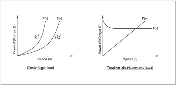
As described above, a NEMA Premium motor will see single-digit efficiency improvements over pre-EPAct motor designs under full load operating conditions. However, in commercial building applications, load requirements change dramatically for HVAC systems based on occupancy and outdoor air temperature. Design day conditions generally represent only a fraction of total runtime for any system. Potential energy savings associated with variable speed pumping for hydronic systems and variable air volume HVAC systems dramatically exceed that associated with NEMA Premium motors. For centrifugal loads such as fans and pumps, this turndown relationship can be roughly simplified as:
So a 100 hp load at 1750 rpm operating at half speed/flow would only require 12.5 hp, while the magnitude of torque would vary roughly as the square of the ratio of speeds at each load. This nonlinear speed/power relationship for centrifugal loads can be exploited for energy saving if the speed of the motor can be changed. For positive displacement loads, such as screw and scroll compressors that require a consistent torque throughout an operation speed range, the associated power to speed turndown relationship is not quite as attractive but still represents a potential for increased energy efficiency.

With an induction motor, the speed of the rotor can be varied with the frequency of the voltage applied to the stator and take advantage of these turndown power/speed relationships. Given this information, it should be clear why the term frequency inverter is interchangeable with the term variable speed drive (VSD).
Ask an engineer the purpose of a frequency inverter (what is frequency inverter?), and a common answer would be "to save energy". While the motivation to increase energy efficiency could be financial (reduced energy costs) or ethical (reduce greenhouse gas emissions associated with power production), it is taken for granted that frequency inverters are an easy way to improve energy efficiency in a motor application. And with these noble intentions in mind, the engineer will specify a frequency inverter for his client.
Oftentimes, that isn't the end of the story for the engineer.
The story sometimes ends badly with a dead motor or a building with power quality issues, an understandably angry client, and a lot of finger-pointing. These outcomes are often the result of a poor understanding of how frequency inverters and motors work in conjunction with the loads they serve. The information and claims from manufacturers and vendors often serve to further confuse the issues. Following are a few basic guiding concepts to dispel some of this confusion surrounding the matching of frequency inverters and motors to fans and pumps typically encountered in commercial building applications.
Anatomy of an induction motor
Electric motors convert electrical energy into rotational mechanical energy. Motors may drive pumps, fans, compressors, or any other number of loads that may be found in a typical building. The concept seems simple, but a review of motor basics is necessary to understand how frequency inverters operate and also how they can destroy a motor.

The most common motor encountered in commercial building multihorsepower applications is a 3-phase ac induction motor. The motor consists of two primary assemblies: a stationary stator and a rotating rotor. Alternating current flows through windings in the stator, creating a rotating magnetic field around the rotor. The frequency of this rotating magnetic field is directly related to the frequency of the ac voltage source. This rotating magnetic field interacts with rotor, inducing current in the rotor and an associated tangential force, which ultimately causes the rotor to turn. In an induction motor, the speed of the rotor is always slower than that of the rotating field. The torque of the motor is roughly proportional to the power of the motor and inversely proportional to the speed of rotation. This operational characteristic is important when considering if a variable torque load (centrifugal fan, pump, or compressor) or a constant torque load (positive displacement screw, scroll, or reciprocating compressor) will be connected to the motor.
The most common type of induction motor is the squirrel cage motor (also called short-circuit rotor type motor). The stator consists of doughnut-shaped sheets of steel called laminations. These laminations have slots punched in them and then are aligned and stacked together. Conductors are then wound through these slots to form coils. These coil conductors are electrically insulated from the laminations. The characteristics of this insulation system are important later in our discussion. The cylindrical rotor fits in the void in the middle of the stator. Like the stator, the rotor is made from stacked steel laminations. These laminations are pressed onto a center shaft. Bars of aluminum or copper are inserted through slots at the outer edge of the lamination and are connected at the ends with shorting rings at either end to form a cage-like structure. The rotor is supported with bearings at the ends of the shaft. There is no direct electrical connection between the rotor and the windings in the stator. The only point of contact is at the bearings, which will be important in a later section.
Induction motors are not 100 percent efficient. Motor energy loss is caused by several factors, including I2R power losses, magnetic core losses, friction losses, and stray load losses. These losses generally result in heat generation, which must be dissipated to preserve the motor winding insulation. For common totally enclosed fan-cooled motors (TEFC), this heat dissipation is accomplished using a fan coupled to the rotor shaft. The speed of the motor will directly affect volume of cooling air produced by this fan. As such, the speed of the motor is an important consideration when variable speed motor operation is desired. As a rule of thumb, a 10 C increase in winding temperature will halve the life expectancy. Conversely, a 10 C decrease in winding temperature will double the life expectancy.
Standard insulation classes for squirrel cage induction motors a
- B (80 C): general purpose
- F (105 C): industrial use
- H (125 C): special use, heavy duty
Premium motors
The government has legislated efficiency standards for electrical motors, beginning with the Energy Policy Act of 1992 (EPAct-1992). Subsequent legislation, the Energy Independence & Security Act of 2007 (EISA-2007), requires that all general purpose, 1 to 200 hp, 3-phase motors rated to 600 V manufactured after Dec. 19, 2010, must meet NEMA Premium motor standards (as defined by NEMA MG1 Table 12-12). Nominal full-load efficiency of these motors ranges anywhere from 77% to 96.2% depending on a number of factors. This represents a low- to mid-single-digit efficiency improvement over pre-EPAct 1992 requirements (see Table 1). While these efficiency improvements may not seem like much, if a motor is run 12 hours a day for 5 days a week, this energy savings during the 3,000 hours of runtime over the course of a year will add up.
Table 1: Motor Efficiency
| Size (hp) | Pre-EPAct1 | EPAct2 | NEMA Premium3 |
| 1.0 | 76.7 | 82.5 | 85.5 |
| 1.5 | 79.1 | 84.0 | 86.5 |
| 2.0 | 80.8 | 84.0 | 86.5 |
| 3.0 | 81.4 | 87.5 | 89.5 |
| 5.0 | 83.3 | 87.5 | 89.5 |
| 7.5 | 85.5 | 89.5 | 91.7 |
| 10.0 | 85.7 | 89.5 | 91.7 |
| 15.0 | 86.6 | 91.0 | 92.4 |
| 20.0 | 88.5 | 91.0 | 93.0 |
| 25.0 | 89.3 | 92.4 | 93.6 |
| 30.0 | 89.6 | 92.4 | 93.6 |
| 40.0 | 90.2 | 93.0 | 94.1 |
| 50.0 | 91.3 | 93.0 | 94.5 |
| 60.0 | 91.8 | 93.6 | 95.0 |
| 75.0 | 91.7 | 94.1 | 95.4 |
| 100.0 | 92.3 | 94.5 | 95.4 |
| 125.0 | 92.2 | 94.5 | 95.4 |
| 150.0 | 93.0 | 95.0 | 95.8 |
| 200.0 | 93.5 | 95.0 | 96.2 |
This motor efficiency chart shows data for totally enclosed fan-cooled (TEFC) motors running at 1800 rpm.
1. Pre-Epact: DOE's MotorMaster+ software version 4.00.01 (9/26/2003) "Average Standard Efficiency" motor defaults 2. EPAct: Energy Polict Act of 19923. NEMA Premium: NEMA MG 1-2003 Table 12-12 frequency inverter or premium motors?
As described above, a NEMA Premium motor will see single-digit efficiency improvements over pre-EPAct motor designs under full load operating conditions. However, in commercial building applications, load requirements change dramatically for HVAC systems based on occupancy and outdoor air temperature. Design day conditions generally represent only a fraction of total runtime for any system. Potential energy savings associated with variable speed pumping for hydronic systems and variable air volume HVAC systems dramatically exceed that associated with NEMA Premium motors. For centrifugal loads such as fans and pumps, this turndown relationship can be roughly simplified as:
HP2 = HP1 (RPM2/RPM1)3
So a 100 hp load at 1750 rpm operating at half speed/flow would only require 12.5 hp, while the magnitude of torque would vary roughly as the square of the ratio of speeds at each load. This nonlinear speed/power relationship for centrifugal loads can be exploited for energy saving if the speed of the motor can be changed. For positive displacement loads, such as screw and scroll compressors that require a consistent torque throughout an operation speed range, the associated power to speed turndown relationship is not quite as attractive but still represents a potential for increased energy efficiency.

With an induction motor, the speed of the rotor can be varied with the frequency of the voltage applied to the stator and take advantage of these turndown power/speed relationships. Given this information, it should be clear why the term frequency inverter is interchangeable with the term variable speed drive (VSD).

 High quality frequency inverters for electric motor speed controls in energy-saving solutions.

