Frequency inverter on pumps for energy saving
Pumps are generally grouped into two broad categories, positive displacement pumps and centrifugal pumps. The vast majority of pumps used today are centrifugal type.
Centrifugal pumps are sized to meet maximum flow rate required by the system. System conditions frequently require reducing flow rate. However, throttling devices - dampers and valves - are installed to adjust pump output. Throttling devices are effective, but not energy efficient. Another method can vary flow and also reduce energy losses. The method: adjust pump impeller speeds so units deliver required flow.
Centrifugal pump operation is defined by two independent curves. One is the pump curve, which is solely a function of pump characteristics. The other is system curve, which depends on size of pipe, length of pipe, number and location of elbows, etc. The intersection of these two curves is called natural operating point, because pump pressure matches system losses.
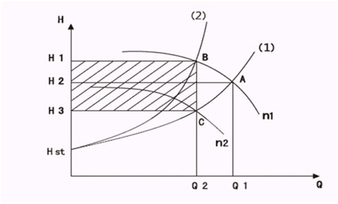
Different from fans, the static pumping head of pumps Hst≠0. The outlet pressure (pumping head) of pumps is required to maintain constant in most occasions. The pump’s energy saving principle can be represented by the diagram.

When decreasing the flow quantity from Q1 to Q2 by the valve, the pump speed maintains its rated speed N1, but the pipe network resistance curve (1) will change to the curve (2), leading the working intersection A to change to B. At this time, the consumed axis power can be represented by the area of H1BOQ2, almost the same to that of H2AOQ1, resulting in huge energy to be wasted.
When the frequency inverter is installed, it can decrease the pump speed from N1 to N2 with the pipe network resistance curve (1) being unchanged, so the working intersection A transfers to C. At this time, the consumed axis power can be represented by the area of H3COQ2. Compared with H1BOQ2, it is easy to find out that the inverter has prominent energy-saving capacity.
Centrifugal pumps are sized to meet maximum flow rate required by the system. System conditions frequently require reducing flow rate. However, throttling devices - dampers and valves - are installed to adjust pump output. Throttling devices are effective, but not energy efficient. Another method can vary flow and also reduce energy losses. The method: adjust pump impeller speeds so units deliver required flow.
Centrifugal pump operation is defined by two independent curves. One is the pump curve, which is solely a function of pump characteristics. The other is system curve, which depends on size of pipe, length of pipe, number and location of elbows, etc. The intersection of these two curves is called natural operating point, because pump pressure matches system losses.
Different from fans, the static pumping head of pumps Hst≠0. The outlet pressure (pumping head) of pumps is required to maintain constant in most occasions. The pump’s energy saving principle can be represented by the diagram.

When decreasing the flow quantity from Q1 to Q2 by the valve, the pump speed maintains its rated speed N1, but the pipe network resistance curve (1) will change to the curve (2), leading the working intersection A to change to B. At this time, the consumed axis power can be represented by the area of H1BOQ2, almost the same to that of H2AOQ1, resulting in huge energy to be wasted.
When the frequency inverter is installed, it can decrease the pump speed from N1 to N2 with the pipe network resistance curve (1) being unchanged, so the working intersection A transfers to C. At this time, the consumed axis power can be represented by the area of H3COQ2. Compared with H1BOQ2, it is easy to find out that the inverter has prominent energy-saving capacity.

 High quality frequency inverters for electric motor speed controls in energy-saving solutions.

